One is the ghost in our minds of a past sensory experience and the other is a physical thing we hope can be a gateway to the first. Does the promise of preserving memories destroy them by creating an unmanageable clutter of infinite possibilities which merge into a cold immaterial surface offering no comfort and condemning us to anxiety?
We want to reclaim power over defining the topology of our interior landscapes. It involves art, hammers, digital storage, authentication, originals, blood, and an evening of fun with people.
If you live in LA, you probably are familiar with huge freeway interchanges. It’s an impressive network of forming a big knot that somehow channels various streams in all the possible ways. It has huge curves sweeping above and below the main wide arteries. Anyway, they are cool. My favorite is where the 110 and 105 interchange and I’ve been mulling over making a cement casting of it for a while now. It starts with grabbing 3D data from the interwebs and turning it into a functional model.
Once the data is prepped, I prepare it for 3D printing. I want the final piece to be 26 inches wide which is wider than any printer I could get my hands on so I break it up in tiles and run some tests.
cut out a tile and make a negative shape
positive and negative tests
Next step is to figure out the process of making the mold. There two options but the first step for each is the same: glue the tiles back together (there will be 16 of them) and use bondo, sand paper to smooth out all the irregularities, and spray paint some urethane to smooth over the result. The question is: should I make the urethane mold directly from the positive 3D prints, or should I create a positive plaster intermediate I can tweak and further polish, and make a mold out of that? If I go with the plaster, I worry that the brittle nature of the plaster and the rigidity of PLA filament will cause the small details to break as I release the plaster image from the 3D print. If I pour the mold directly on the 3D print, I worry that the tell tale 3D print lines will be captured by the mold and that I will not have had the chance to polish it with the control a plaster intermediate would give.
So, next step is to test both approaches on my two test prints, and also test printing a tile with PETG filament which I hear is more flexible. If you have any recommendations, I’m all ears…
The long awaited part 2 of this blog post has finally arrived! Though I’ve been tinkering on this project for the past two years, I decided to write it up to coincide with the outrageous arrest of 14 year old tinkerer Ahmed Mohamed who was hand cuffed because his teacher thought his electronic clock project looked like a bomb. This binary clock project of mine ended up being a personal electronic circuit design introduction course. You can download all the relevant files here if you want to make your own.<br />I forgot what the original inspiration was but what I’m ending up with is a working binary clock on a custom printed circuit board. Ultimately, this project will involve fiber optics inside polished cement for a unique time piece but we’re not there yet… Here’s what I learned so far:
Bit shifters
A binary clock needs 20 individual blinky things and the arduino has less than that, so I needed to figure out a way to create more individually addressable outputs. The solution I found is a the 74HC595N chip that can turn two inputs into 8. In fact, you can wire them in series and they can provide you with any number of outputs in multiples of 8. I decided to use one to drive the hours display, one for the minutes, and one for the seconds.
There are tons of tutorials for them so it was fairly straight forward to get it working.
Keeping time
While you can make a timer with just an arduino, it is not very accurate and it has no way to keep the clock going if you unplug the power. I used a rtc1307 chip which is designed for just this purpose. It keeps time accurately and uses a small battery to continue keeping time when the power is disconnected.
Again, there is an arduino library available and a good amount of tutorials out there so it wasn’t too hard to test it and incorporate it in the build.
Removing the arduino
Eventually, since I wanted to end up with a single circuit board, I didn’t want to have to plug anyting into an arduino. Once again, the internet is a wonderful resource which allowed me to figure out how put only the arduino components I needed onto a bread board. I can upload the code onto the chip by putting it on an arduino, and then pull it off of there to mount it directly onto the breadboard.
Code
The clock can be set to one of 4 modes: display time, set hours, set minutes or set seconds. There are two buttons. One button toggles between all the different modes, while the other increments the count of the hours, minutes, and seconds when they are in their respective mode.
//Pin connected to ST_CP of 74HC595 const int latchPin = 8; //Pin connected to SH_CP of 74HC595 const int clockPin = 12; ////Pin connected to DS of 74HC595 const int dataPin = 11;
//Pins for setting the time const int button0Pin = 5; const int button1Pin = 6;
// Variables for debounce int button0State; int button1State; int previousButton0State = LOW; int previousButton1State = LOW;
long lastDebounce0Time = 0; // the last time the output pin was toggled long lastDebounce1Time = 0; // the last time the output pin was toggled long debounceDelay = 50; // the debounce time; increase if the output flickers int button0Mode = 0;
// object to communicate with RTC tmElements_t tm;
void setup() { // Setup pins for the shift register pinMode(latchPin, OUTPUT); pinMode(clockPin, OUTPUT); pinMode(dataPin, OUTPUT);
// Setup pins for manual time setting pinMode(button0Pin, INPUT); pinMode(button1Pin, INPUT); }
void loop() {
RTC.read(tm); // button 0 can be in display time, hour set, minute set, and second set modes. // if( button0Mode == 0){ timeDisplayMode(); } else if( button0Mode == 1){ setHourMode(); } else if( button0Mode == 2){ setMinuteMode(); } else if( button0Mode == 3){ setSecondMode(); }
// // mode switching // // Just after a button is pushed or released, there is noise where the value returned is 0/1 random. // debouncing consists of reading the incomming value and, if it has changed, storing the time the change was noticed. // It then continues to check and if after a certain amount of time (delay), it reads the input value and it is still the changed value // noticed before, then it means that an actual state change happened. int reading0 = digitalRead(button0Pin); // this only happens when the input value is different from the last time the value was read if (reading0 != previousButton0State) { lastDebounce0Time = millis(); } // we only enter this loop if the returned value hasn’t changed in a while, which means we are not in the noisy transition if ((millis() – lastDebounce0Time) > debounceDelay) { // if we are in here, it means we got two similar readings. if (reading0 != button0State) { // if the two similar readings we got are different from the stored state, we must have changed button0State = reading0; if(reading0 == HIGH){ button0Mode = (button0Mode+1)%4; } } } previousButton0State = reading0;
// create binary value for each digit of the hour/minute/second number // offset represents how many bits are used for the tens. int setTimeBits(int n, int offset){ int n1 = n%10; int n0 = (n-n1)/10; return n0 | n1<<offset; }
Schematic and board
Once the breadboard was working, I set out to sketch the circuit in Fritzing. While it’s not quite as intimidating as EAGLE cad, I ended up using the latter after running into some limitations with the former (I don’t remember what they were). There was a lot for me to learn there but, in the end, it’s conceptually pretty simple: all the pieces have to be connected together correctly. It’s just another way to represent the circuit. Once that was done, I started with the board. I laid out all the components and let the software automatically figure out how to create the correct traces. One cool thing is that if you choose the correct electronic components in the software, all the size and shapes are properly represented when you are designing the board. It’s a huge pain in the ass to sort through all the libraries of components, though, specially when you don’t know what all the specs mean.
The eagle cad files are included in the download file at the top of this page.
Manufacturing the board
Super simple: just go online and find a service that will manufacture them. For this project, I used oshpark.com and dirtypcbs.com, which allow you to upload your designs right out of EAGLE cad. After a few weeks, you get your board in the mail, ready for you to solder the components on. I order my components from mouser.com, which allows you to save a collection of various components into a project specific list. Again, finding the right components amongst the tens of thousands they have available is really time consuming and annoying. But now, I have my parts list so I never have to go through that again if I want to solder up new versions of the board. The list of parts in included in the download file at the top of this page.
The ugly truth
If you were paying attention, you no doubt noticed in the preceding paragraph that I used two board manufacturers. That is because the first board layouts I had printed actually had shorts. I suppose it’s probably not that uncommon, but it’s really frustrating to upload your designs, order the boards, wait for them to be delivered, spend all this time soldering the board to find out it doesn’t work, and then it can be challenging to figure out where the wires are getting crossed. In the end, I spent about $150 on boards and parts that ended up not working. I guess that’s the cost of learning… My first two board designs were ordered through Oshpark, and the minimum order was 3, for about $50. The third order was done on dirtypcbs and was $25 for 10 boards. They feel cheaper and took forever to get delivered but you sure can’t beat the price.
This month, I am deciding to make bigger and heavier pots, but still keeping with the monolithic shapes. I was spurred into creative action by a cardboard tube I saw in a trash pile at work. I noticed it and a lightbulb flashed in my head; I immediately grabbed it, knowing exactly what I was going to do with it. The world is full of gifts indeed and I love the process of finding sudden and unexpected inspiration at random time. All you have to do is remain open, hone your discernment skills, and channel whatever comes your way. Also, I’m experimenting with black cement coloring and black river rocks on my old 6 inch round model.
These pots, or ones that look like it, are available for sale, ranging from $30 to $100. I hand polish them myself to a nice smooth finish with a cement grinder that reveals the pattern of the aggregate, and for the amount of labor I put in them, I really can’t afford to have you buy them, but hey: my house can only accommodate so many of them so I have to somehow get rid of them. I do not have a store set up but leave a message or email me and I’m sure we can figure out something.
Good question. Yeah, yeah… I know: I said I was building a big 20×24 camera but I have written nothing about it in the last 4 months. Was I just a tease? Was I showing off before actually delivering the goods?
In a word: yes. I got to a place where “Things Got Complicated” and I wasn’t sure what the next smart step was. Solving the building challenges started to feel like work. So I did what sane people do when faced with challenges: I walked away… I’m sure it is an affront to some notion of puritanical work ethic dictating that one doggedly apply oneself to a problem until finally overcoming it. Cue in the inspirational music celebrating triumph over adversity, drink the cool-aid, master your id, pay your taxes.
Except we’re talking about Relentless Play, not Relentless Work. It’s about engaging in what feels good rather than bowing to some flawed abstract concept of what should be.
I am still very determined to see the project through; I just don’t feel it right now. I need to let it sit for a while and let the correct path forward bubble up into my consciousness on its own, specially since it will end up costing a a fair amount of time and money to make. Basically, my problem is I don’t know what the hell I’m doing. I bought some 80/20 extrusion to serve as a base and some linear bearing carriages for the lens mount and the film back to slide on but they are pretty heavy and I need to figure out a way to keep them steady. Also, I need to figure out what we are going to do about bellows. Whatever it is, it needs to be built well enough to not bleed a bunch of light in the camera and onto the plate.
Some people like to have a project fully planned out before they go into action. Me, I typically like to figure it out as I go along. In fact, once I’ve done something and have a clear idea on how to go from A to Z, I’m not really that interested anymore.
Anyway, I have a lot of other similarly on hold projects and I picked a few back up in the meantime so it’s not like I’m giving up.
Broken things are solutions looking for problems. They hold magic undiscovered potential. I hate throwing away broken things because I’m never sure I won’t be able to later re-purpose some part of them into something else. On a seemingly unrelated note, I’m often in need of plugging some random computer or video device in to a screen for testing and, up until now, I have had to swap cables on my desktop monitors or pull out some bulky crappy old monitor from the garage and find some temporary place for it while I use it. What I really want is a small lightweight monitor I can easily access and occasionally plug a Raspberry Pi or my linux server into, something that’s closer in size to a laptop screen than a big bulky desktop monitor and that will not take up desk space.
Cue in broken hardware
As luck would have it, my stupid cat likes to sleep on laptops. They provide a nice warm place and a soothing fan sound. Usually, the only repercussion of this fact is that I sometimes wake up in the morning with hair on the keyboard and the Google helpfully informing me that
In one particular instance however, I was using a hackintoshed Asus 1201N that was clearly not designed to support the weight of a house cat; I know because it never woke up from its night of feline suffocation. I took it apart to see what I could find but never did find the needle in that haystack; probably a shorted motherboard… In the closet of broken stuff it went.
A killer and his victim
Displays
I’m always thinking about creating different displays. I’m pretty bored with the standard monitor design and I’m always interested in challenges to the rectangle-in-a-sleek-shiny-enclosure status-quo which led me to learn that I could probably find hardware compatible with my broken laptop’s LCD panel. I took the laptop apart, got the part number of the LCD panel and eventually found the right board on ebay for about $30 (I searched for “HSD121PHW1 controller”, HSD121PHW1 being the panel’s model number). Two weeks later, the padded envelope with the telltale Chinese characters on it showed up in my mail mailbox and I immediately plugged it in to test it. Lo and behold, it worked!
From parts to a thing
Okay, so now, I actually have the parts I need to make that small monitor I’ve been wanting: a small LCD panel and a driver board I can plug any HDMI or DVI display into. The next step is putting it together in a cool, cheap and convenient way. I had been peripherally interested by Plexiglas for another project so I decided to try it as a mounting surface for this. I measured the width of the screen and driver board, as well as the height of the screen with and without the adjustment buttons, and got a couple pieces cut at my local plastic store (Santa Monica Plastics). I drilled some holes, mounted the various parts on the back using standoffs, and sandwiched them by screwing in the smaller piece of plexi in the front using longer standoffs.
The area of a tintype image that gets exposed to the most light essentially becomes a pure silver coating. While the reflective properties of silver make the final image a bit darker than traditional photographic prints, it also gives it a really compelling silvery metallic reflective feel. As a way to highlight those unique qualities, I decided to experiment with hiding LEDs in a box frame to illuminate the image from inside. I also wanted to find a way to intensify the lighting and make the image come alive as viewers got close to it.
Framed!
I inherited some antique oak wood floor pieces and made quick work of it on the old chop saw.
I built some walls behind the front of the frame and attached some LED string lights on it.
I mounted an 8×10 tintype on a black backing board cut to fit at the bottom of the frame’s walls.
Lights OFF / Lights ON
Controls
The next step was to figure out the kind of sensor needed to make the lights come on as a viewer approached the frame. I figured the sensor required would need a range of at least a few meters and be able to return the specific distance to the closest obstructing object. I am not a distance sensor expert so I used the internet to help. In the end, I settled for a Maxsonar EZ0 LV. It’s cheap, it’s got a range of a few meters and it’s got both serial, analog and PWM outputs. I hooked it up to a teensy board and confirmed the sensor was returning appropriate distance values. On the lighting front, I was planning on controlling the brightness of the LED string with the teensy, but since the LED string requires a 12V supply and the teensy outputs only 5V, I used a MOSFET driven by the teensy’s output to modulate the LED’s power supply.
The electronically savvy amongst you will notice that I’m currently using 2 power plugs: a 12V one for the LED and a 5V USB supply for the teensy, which is stupid. I tried to use a voltage regulator to convert the 12V to a 5V supply but somehow it created much noisier reading on the distance sensor… I must have missed a capacitor somewhere. I will try using an Arduino Nano which can take a 12V supply directly.
Code
God, I love the internet!!! I read somewhere that the sensor’s PWM signal was much cleaner so I started with that but I eventually found out that it also is much much slower and wasn’t able to keep up with the rate of change I was looking for. In the end, I used the analog signal and tried to filter it as best I could.
/*
Using the Analog signal from a Maxsonar LV EZ0 to drive a
12V LED strip through a MOSFET.
Take 20 samples, sort and select the median value.
*/

const int anPin = 9;
int anVolt, cm;
const int samples = 20;
int ranges[samples];
int highestReading;

float time;
float previousIntensity;
float maxDist;
float minDist;
int minVal, maxVal;

int mosfetPin = 9;           // the pin that the MOSFET is attached to

void setup()  {
  // declare pin 9 to be an output:
  pinMode(led, OUTPUT);
  Serial.begin(9600);
  time = 0;
  maxDist = 450;
  minDist = 10;
  minVal = 5;
  maxVal = 255;
  previousIntensity = 0;
}

void loop(){
  // print time spent since last loop
  Serial.println(millis()-time);
  time = millis();

  // sample sensor value
  for(int i = 0; i < samples ; i++)
  {
    anVolt = analogRead(anPin)/2;
    ranges[i] = anVolt;
    delayMicroseconds(50);
  }
  isort(ranges,samples);

  // convert to centimeters
  Serial.println(samples/2);
  cm = 2.54 * ranges[samples/2];

  // shape the curve of the result
  float intensity = (cm - minDist)/(maxDist - minDist);
  intensity = 1-constrain(intensity,0,1);
  intensity = intensity*intensity;
  intensity = previousIntensity*.995 + intensity*.005;
  previousIntensity = intensity;

  // set the brightness of pin 9:
  float val= intensity*(maxVal-minVal)+minVal;
  analogWrite(mosfetPin, val);
}

//Sorting function
void isort(int *a, int n){
// *a is an array pointer function
  for (int i = 1; i < n; ++i)
  {
    int j = a[i];
    int k;
    for (k = i - 1; (k >= 0) && (j < a[k]); k--)
    {
      a[k + 1] = a[k];
    }
    a[k + 1] = j;
  }
}
Next Steps
Once I get my paws on that Arduino Nano board, I can rework my circuit and get the soldering iron out to make my electronics more permanent. I have also ordered a HC-SR04 Distance Sensor to see how it compares to the Maxsonar in terms of accuracy, speed and noise. Also, I need to make the frame a little bit deeper so the light can spread out a bit further across the image.
Which one is cooler?
The ominous cyclopean look or the cute and friendly Wall-E look?
One of the cool things about a camera is that at its core, it’s very simple. All you need is a lens that focuses light and a surface that this light gets focused on. The process of bending light with lenses to focus on a surface was first explored during the Renaissance with the camera obscura. It wasn’t until the 19th century that people figured out how to keep a record of how much light hit a particular area of that surface. Anyway, to make a camera, all you really need is a lens and a surface for the light to hit, and to create an image from a camera, you either need to trace the image you see projected on the surface or you need some kind of coating on the surface that reacts to light.
Is that a large lens in your pocket?
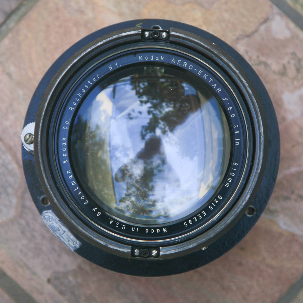
After giving me a taste of 4×5 tintypes, my buddy at Tintypebooth showed me some large old lenses from photographic systems used in spy planes that he had bought on ebay. These things are serious! They are very heavy and the glass is super thick; there is just something massive about them, and when you hold one and feel its weight, you can’t help but be awed by their image making potential and you get possessed by an urge to unlock that potential. He pitched the idea of building a ultra large format camera with one of them, a little “Kodak Aero-Ektar 24” 610mm” number, weighing in at just over 10 lbs and sporting a few scratches I like to think were caused by the strafing of some of the Luftwaffe’s last Messerschmitts.
Let’s decode those numbers, shall we? The 24” is the size of the image plane and 610mm (also 24”) is the focal length.Based on my previous post about lenses, it means that at its shortest, this camera will be a little over two feet long. At four feet of distance between the lens and the plane, the image on the focal plane will be the same size as the subject in focus four feet from the lens, and six feet will create an image bigger than reality. The film holder will need to accommodate plates that will be 24 inches on one side. I may need a bigger car…
I need a plan
Patience is a virtue I’ve always been in somewhat limited supply of. We have this killer lens… What’s the fastest and cheapest way we can get a picture out of it? Sure, we can design a fancy camera with a lot of bells and whistles but it would take a long time and cost a pretty penny. For now, I just need a bare bones proof of concept prototype. I’ll focus on the basic pieces and see if I can build it myself. I’ll build the back out of oak and do all the struts and supports using aluminum channels. The animated image above is a Maya model I built to scale that shows how all the pieces need to fit together. It doesn’t look too difficult, does it? One thing not shown in the animation is that the back that will hold the plate will be interchangeable with another back that will have the ground glass necessary to focus. The process will be as follows: first you will use the ground glass back to focus, slide it out, and then slide in the film back to load your camera.
Baby got back
Kim Kardashian’s got nothing on this bad boy! I built this 24″x20″ film back over the past couple weeks. I’m not a great builder and my Home Depot tools are a bit wobbly so I wouldn’t call it fine craftsmanship but it will hopefully do the trick. Oh, and did I forget to mention it’s not exactly square? Yeah… Let’s just say it’s square enough. It’s made from 1″x2″ and 1/4″x2″ red oak lumber which I routed to get the insets. It will make a great example when we eventually hire a finish carpenter for the next fancy version of the camera. Here are some pictures of the various pieces it’s made of (you can also see that I like to wear my slippers when I take pictures of my handy work).
More to come…
Here are the steps that come next and will be documented in a hopefully not too distant future.
I already bought the aluminum extrusions that are necessary to build the film back support, the lens plate holder, and the rails. I will need to learn how to properly drill in aluminum and figure out how to connect all the pieces. (anyone in Venice with a drill press?)
I will built the lens plate, mount the lens on the plate, and mount the plate on the rails.
Last will be creating the bellows. Not too sure how that will work but what the hell! We’ve got a few ideas. I’m sure we’ll figure something out.
If you have a teenager, you will no doubt be familiar with the dilemma of letting them listen to music at night while keeping them somewhat sheltered from the irresistible pull of the bright rectangle of light that seem to so efficiently hijack their attention. In my day, it was simple: the tape deck played music and that’s all it did. These days, with smart phones, it feels like it’s all or nothing. The tape deck comes with a movie theater, a video game arcade, and a place to hang out with friends, and they’re all open and available 24 hours a day. So, like any concerned parent, we take the phone away at night but since now days, it’s the place they get their music, it means they can’t listen to music anymore which is kind of sad.
Something annoying:
You know what I hate? The fact that our consumer culture dictates that when something is broken, we throw it away and buy something new rather than fixing it. I had a smartphone and after two years, the internal phone speaker broke, which meant I had to have it on speaker or plugged into an earpiece to hear people talking to me. I actually attempted to fix the problem: I ordered the part on ebay and spend 30 minutes opening the phone but I failed. Mind you, the smartphone was still a computer with over 1000 times the speed and memory of my first computer, a nice bright and sharp touch screen, wifi, etc… Other than the speaker problem, it worked perfectly. In the end, though, since I couldn’t fix the problem, I reluctantly gave in and bought a new phone. Grrrrr!
Ready for the trash? Not so fast!
Ready for the trash? Not so fast!
So, I made this:
It’s actually really simple. I tried to restrict the functionality of the phone and create an object designed with the single purpose of enjoying spotify without the potential distraction of the rest of the internet getting in the way. First off, with the zip card out, your smartphone becomes a small tablet.
I removed all the video games and Netflix and Youtubes and Hulus and Snapchats and Facebooks and Vines and Instagrams and circles and Pinterests and Ellos and MySpace. I kept only Spotify and installed a program called Autostart which automatically launches an app after the phone boots and prevents a user from quitting the app.
I then built a frame into which I could mount the phone and poured a trademark Hollier polished cement base. I used autostart to automatically launch Spotify to whenever the phone turns on and thus transformed a crappy old orphaned phone into a custom one-of-a-kind Spotify appliance. Being mounted in a frame and set into a solid base transforms it into something you set and walk away like a radio rather than something you interact and fiddle with like a phone.
Repurposing an old smartphone into a custom spotify outlet